· Orion Delta Team · Technology · 10 min read
Shared-Aperture LiDAR and Radar
A transparent metamaterial mesh enabling combined LiDAR, radar, and heating through a single window.
Autonomous perception systems, in automotive Level 3+, in counter-UAS towers, in outdoor industrial robotics, in unmanned aerial systems for beyond-visual-line-of-sight flight, increasingly require complementary LiDAR and radar sensing. The two modalities have largely orthogonal failure modes. LiDAR provides high-resolution three-dimensional point clouds with deterministic depth but degrades sharply in fog, dust, and precipitation. Radar offers all-weather operation and intrinsic Doppler velocity measurement, at coarser angular resolution. The combination is increasingly mandated, not optional.
The dominant commercial implementation today is software fusion of physically separate sensors: each modality occupies its own optical or radio-frequency window, with measurement vectors fused at the object or feature level in downstream compute. This carries persistent penalties, spatial parallax between fields of view, drift in extrinsic calibration over the system lifetime, doubled bill of materials and failure surfaces, and a packaging volume that constrains vehicle styling, drone payload mass, and industrial sensor count.
A more compact, more robust architecture exists in principle: a shared optical and radio-frequency aperture through which both modalities propagate. The defense missile-seeker community has been pursuing it since the 1990s. Commercial translation to the 905 nm or 1550 nm LiDAR plus 76–81 GHz mmWave radar bands has not occurred. The obstacle is materials: a single passive window cannot be simultaneously optically transparent and electromagnetically conductive at these wavelengths using conventional engineering materials. This article describes an architecture that closes the materials gap, enabled by a transparent metamaterial mesh.
Why combined sensing is now mandated
The regulatory drivers are now consistent across four verticals.
In automotive, UN Regulation 157 (Automated Lane Keeping Systems) and the Euro NCAP 2026 protocols effectively require LiDAR alongside radar for Level 3+ vehicle certification. The two certified production L3 systems in the market today, Mercedes Drive Pilot and BMW Personal Pilot, combine Valeo SCALA or Innoviz One LiDAR with separately-housed radar.
In industrial robotics, ISO 3691-4:2023 and IEC TS 62998-1 mandate dual-modality safety perception for driverless industrial trucks operating in environments with dust, condensation, or restricted optical visibility, explicitly identifying radar as the complementary modality where LiDAR safety scanners degrade.
In aviation, the FAA Part 108 BVLOS rulemaking (expected to be finalised in mid-2026) institutionalises radar-based detect-and-avoid for commercial drone operations alongside primary cameras and LiDAR. Equivalent EASA SORA 2.5 implementation guidance has been in place since 2025.
In defense, counter-UAS programmes across NATO, EU member states, and the US Department of Defense routinely specify combined radar + electro-optical + (increasingly) LiDAR sensor heads for fixed-site and vehicle-mounted protection of airfields, military bases, and critical infrastructure.
The architectural conclusion is the same across all four: dual-modality LiDAR + radar is becoming the regulatory floor. The open question is how the combination is integrated.
The integration problem
There are three tiers of integration available to system designers.
Software fusion describes the dominant pattern, discrete LiDAR and radar sensors, each with its own optical or RF window, fused at the data tier in downstream compute. Almost every commercial automotive, robotics, and counter-UAS product on the market today operates this way.
Module integration describes a single enclosure containing physically separate LiDAR and radar sensors with shared power, compute, and time-synchronisation. Waymo’s roof-pod patents describe this architecture for robotaxi platforms; the patents do not eliminate the need for separate optical and RF windows inside the housing.
Hardware integration describes a shared optical and radio-frequency aperture through which both modalities operate, with shared boresight, shared calibration, and shared environmental conditioning, defog, defrost, and cleaning all performed through a single surface.
The defense missile-seeker community has been doing hardware integration for over thirty years, Lockheed Martin’s US 6,262,800 (dual-mode semi-active-laser / LADAR seeker), Raytheon’s US 7,786,418 (multimode RF and imaging-infrared with RF-transparent baffles), and Raytheon’s more recent US 11,394,116 (2022, dual optical and RF phased-array photonic integrated circuit) are representative. These filings are concentrated in mid-wave infrared, W-band radar, and semi-active laser bands, and do not extend to the 905 nm / 1550 nm LiDAR plus 76–81 GHz radar combination that commercial automotive, industrial, and UAV applications require.
In academia, combined microwave-photonic radar and LiDAR have been demonstrated on single silicon-on-insulator photonic integrated circuits (Ghelfi et al., Nature 2014; Scotti et al., Optics Letters 2015; Onori et al., IEEE JLT 2020) but at technology-readiness levels of 3–4.
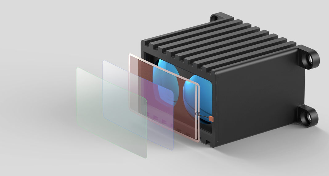
The shared-aperture architecture
The shared aperture is a single passive window through which three classes of signal propagate. First, optical signals, LiDAR transmit and receive at 905 nm or 1550 nm, and electro-optical or infrared camera signals at visible and near-infrared bands. Second, radio-frequency signals at the automotive-radar bands (76–81 GHz), transmitted and received by an antenna structure integral to the window itself. Third, resistive heating power delivered uniformly across the window surface for defog and de-ice, using the same conductive structures that constitute the RF antenna.
The functional requirements are demanding:
| Parameter | Target | Driver |
|---|---|---|
| Optical transmission (visible + near-IR) | > 90 % | LiDAR and EO/camera signal integrity |
| Optical haze | < 1 % | Imaging-grade clarity |
| Sheet resistance | < 5 Ω/sq | Antenna performance and heater power |
| Insertion loss at 77 GHz | < 2 dB | Radar link budget |
| Wire width | sub-optical-wavelength | Visual invisibility |
| Mechanical compliance | tolerates flex and curvature | Curved housings and windshields |
| Thermal stability | −40 to +85 °C | Automotive operational envelope |
No conventional material meets all of these simultaneously. Indium tin oxide (ITO) meets the sheet-resistance criterion only weakly (typically 10–100 Ω/sq), fails the patterning criterion for RF antenna geometry, and fractures under mechanical flex. Solid metallic thin films meet the conductivity criteria but fail optical transmission. Silver nanowire networks, carbon-nanotube films, and graphene electrodes (reviewed in van de Groep et al., Nano Letters 2012) offer partial improvements but do not provide the antenna patterning fidelity that mmWave operation requires.
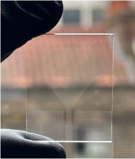
The transparent metamaterial mesh
The metamaterial mesh is a planar lithographically-defined pattern of metallic wires deposited on a transparent substrate. The geometry is small enough to be invisible to the eye and large enough to be electrically continuous at radar frequencies. Wire thickness is 1–3 µm, wire width is approximately 1 µm (roughly a hundredth of the width of a human hair), and the mesh pitch is selectable from 10 to 100 µm depending on the application’s radio-frequency, optical, and thermal trade-offs.
The geometric principle is straightforward. At LiDAR wavelengths in the near-infrared (λ ≈ 0.9–1.55 µm), individual conductive wires of micrometre width are sub-wavelength scatterers and the open area between them dominates transmission, the mesh appears transparent. At mmWave radar frequencies, where λ ≈ 3.9 mm at 77 GHz, the same wire array is far smaller than the wavelength and presents itself to the radar field as an essentially continuous metallic surface that can be patterned into antenna elements, transmission lines, feed networks, and beam-steering metasurfaces.
A representative parameterisation for 76–81 GHz automotive radar is a 30–50 µm-pitch silver mesh of 2 µm wire thickness on a borosilicate or polymer-film substrate. This achieves optical transmission greater than 90 % at both 905 nm and 1550 nm, sheet resistance in the 0.2–5 Ω/sq range, and 77 GHz low insertion loss. Mesh pitch is the dominant design variable: smaller pitch reduces sheet resistance (improving antenna and heater performance) but raises optical haze and risks visible-band moiré effects; larger pitch preserves the optical performance of the bare substrate but degrades the radio-frequency and thermal performance.
Beyond uniform grids, the mesh can be lithographically patterned for specific RF antenna geometries (patch arrays, slot arrays, MIMO configurations), for frequency-selective surface behaviour, for beam-steering metasurfaces redirecting the principal radar lobe toward operationally relevant angles, and for non-uniform mesh density delivering locally-enhanced heating across windows of irregular shape.
The mesh structure consumes approximately 80–90 % less raw metal by volume than a solid metallic film of equivalent effective conductivity, a meaningful contributor to unit-area cost and supply-chain resilience at scale. Compared with silver nanowire networks, which share the metallic-mesh advantage of low sheet resistance with high transparency, the lithographic mesh provides the precise antenna patterning that stochastic-geometry networks cannot. Compared with ITO, it provides both the patterning flexibility and the mechanical compliance required for curved-window applications.
Industrial fabrication uses either roll-to-roll lithography on flexible substrates (suitable for large-area automotive and industrial windows) or direct-write patterning on rigid glass. Characterisation methods include optical transmission and haze measurement per ASTM D1003, four-point probe sheet-resistance and S-parameter extraction, anechoic-chamber antenna pattern measurement against solid-metal references, and flex- and thermal-cycling protocols at automotive-grade ranges.
Functional integration
The mesh supports three concurrent functions within a single film deposition.
LiDAR transmit and receive at 905 nm or 1550 nm propagate through the mesh with losses determined by fill factor; for the representative parameterisation above the loss is below 10 %. Wide-spectrum camera and electro-optical signals at visible and near-infrared wavelengths share the same window without modification.
The patterned mesh is lithographically configured into the chosen RF antenna geometry, most commonly an array of patch antennas with integrated feed network for 76–81 GHz operation. Radiating elements, ground plane, feed lines, baluns, and impedance-matching networks are realised in the same film deposition. MIMO configurations supporting multiple simultaneous radar channels, and beam-steering metasurfaces redirecting the principal radiation lobe, are accessible without additional film layers.
Connected to a low-voltage source, the same conductive structure operates as a transparent resistive heater. Mesh uniformity produces uniform power dissipation; deliberate variation of mesh pitch introduces locally-enhanced heating where required. Typical operating power at automotive windshield scale is in the few-watt range. The three functions are electrically and electromagnetically distinguishable, radar at 76–81 GHz, heater at DC or low-frequency AC, optical signals decoupled from both, so integration trade-offs concern mesh geometry rather than functional cross-talk.
Application domains
Four primary autonomous-perception verticals where the shared-aperture architecture applies, with their associated regulatory drivers.
In automotive Level 3+ ADAS, behind-windshield integration of LiDAR and forward radar through a shared window solves the persistent contamination problem of behind-bumper radar placement, while sharing a single defog control loop with the existing windshield heating budget. The architecture supports both 905 nm and 1550 nm LiDAR alongside the 76–81 GHz radar band.
In counter-UAS systems, the single-aperture form factor reduces the radome and optical-window count on fixed-site and vehicle-mounted sensor heads. Integrated heating supports all-weather operation in fog, ice, and dust environments characteristic of fixed-site protection of airfields, military bases, and critical infrastructure. The window admits co-located electro-optical and infrared imaging.
In industrial safety, outdoor autonomy in sawmills, ports, mining sites, and food-processing environments requires both LiDAR resolution and radar penetration of dust and condensation. A single PLd / SIL2-rated combined sensor through a heated transparent window addresses the ISO 3691-4:2023 dual-modality requirement within a single certified enclosure.
In UAV detect-and-avoid, sub-kilogram, sub-15-watt airborne combined LiDAR-radar sensors become feasible through the shared-aperture geometry, with relevance to FAA Part 108 BVLOS commercial operations and to defense ISR payloads where size, weight, and power constraints are particularly stringent.
Contact us
If you are a Tier 1 automotive supplier or OEM evaluating Level 3+ sensor architecture for the next programme window, the metamaterial mesh integrates with the front fascia and the windshield in ways that are not possible with incumbent transparent conductors.
If you are a defense prime or counter-UAS integrator designing the next-generation sensor head, single-aperture, heated, all-weather, multi-band, we have the platform technology to make a difference.
If you are an AMR or industrial-automation OEM building outdoor autonomy in dusty, wet, or icy environments, the safety-certifiable single-housing combined sensor is something we are actively scoping with Tier 1 partners.
If you are an investor tracking the convergence of LiDAR, radar, photonics, and metamaterials, the underlying market and IP landscape research that informed this article is available on request.
Reach out: info@oriondtech.com.