· Orion Delta Team · Technology · 12 min read
Transparent Phased-Array LEO Satcom
A transparent phased-array antenna laminated into the panoramic roof, enabling vehicle-to-LEO broadband on Ku- and Ka-band.

The connected and autonomous car needs always-on, low-latency, global broadband, for high-definition map updates, over-the-air software, remote services, in-vehicle entertainment, and the redundancy that Level 3+ autonomy demands. Terrestrial cellular networks deliver this within their coverage envelope; outside it, in rural areas, in tunnels, across borders, in motorway dead zones, they do not. The complement is Low-Earth-orbit (LEO) satellite broadband, which is now operational at scale across multiple commercial constellations. Direct vehicle-to-satellite connectivity is technically proven, regulated, and standardised.
The bottleneck is the antenna on the car.
Every commercial vehicle satellite terminal on the market today is opaque, externally roof-mounted, between four and ten centimetres tall, and visually disruptive. These terminals are acceptable on a long-haul truck, an emergency-response vehicle, an RV, or a maritime hull. They are not acceptable on a premium passenger car with a panoramic glass roof. The vehicle styling team and the wind-tunnel engineer have a veto and they exercise it, and so the rest of the value chain, the constellation, the modem, the digital services, waits for a terminal that fits the modern vehicle.
That terminal is what this article is about: an electronically steerable phased-array antenna that is transparent and laminates into the panoramic glass roof or windscreen. Invisible to the driver and passenger, it operates as a full-performance Ku-band LEO satcom terminal, with a Ka-band roadmap. The enabling material is a transparent metamaterial mesh developed by Orion Delta, and the architectural move that closes the integration is an edge-embedded transceiver coupled to the radiating layer through a non-contact RF transition. The barrier the technology clears is not standards or regulation, both have arrived. The barrier is materials: until recently no transparent conductor combined the optical clarity, the sheet resistance, and the antenna-patternable fidelity that a Ku- or Ka-band phased array requires. The Orion mesh is that material.
The materials problem
A phased array at satellite frequencies needs a conductor that is simultaneously transparent enough to disappear in glazing, conductive enough to operate as a low-loss antenna at 10–30 GHz, and patternable into precise antenna geometries with micron-scale fidelity. The conventional candidates all fall short of this combination.
Indium tin oxide (ITO), the workhorse transparent conductor of touchscreens and displays, has sheet resistance of 10–100 Ω/sq at high transparency, two orders of magnitude away from what a satcom array needs. It is also brittle, and it fractures under the mechanical flex that curved automotive glass imposes.
Silver nanowire networks improve the conductivity-transparency trade-off but cannot be patterned into the precise antenna geometries that millimetre-wave operation requires. Random network topology is incompatible with the wavelength-scale element placement of a phased array.
Copper macro-meshes, patterned conductive grids with wires thick enough to be visible, solve the conductivity problem and the patterning problem but fail the transparency requirement. The driver can see them.
Carbon-nanotube films, conductive polymers, and graphene electrodes have been published as transparent-antenna research substrates but do not, on the available evidence, scale to the patternable, low-loss, antenna-grade conductor that a >27 dBi Ku- or Ka-band phased array requires. To the best of our knowledge, no fully transparent electronically steerable Ku- or Ka-band phased array has been publicly reported in production-relevant form.
Compounding this, integrated-circuit electronics, amplifiers, mixers, filters, phase shifters, beamforming ASICs, cannot be made transparent. A phased array requires hundreds of these per aperture. A transparent phased array therefore cannot be transparent everywhere; it has to find an architecture that puts the radiating layer in the glass and the active electronics behind, beside, or around it, while preserving signal integrity across the boundary. Closing this architectural problem is what the metamaterial mesh, together with an edge-embedded transceiver and a non-contact RF transition, accomplishes.
The transparent metamaterial mesh
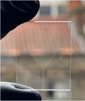
The mesh is a planar lithographically defined pattern of metallic wires deposited on a transparent substrate. Wire thickness is 1–3 µm, wire width is approximately 1 µm, roughly one hundredth of the width of a human hair, and the mesh pitch is selectable from 10 to 100 µm depending on application trade-offs. The geometry is small enough to be invisible to the unaided eye and large enough to be electrically continuous at radar and satcom frequencies.
The geometric principle is straightforward. At visible wavelengths the individual wires are sub-wavelength scatterers and the open area between them dominates transmission, the mesh appears transparent, with optical transmission above 90% in representative parameterisations. At satcom frequencies, where the wavelength is one to three centimetres (Ku: λ ≈ 21–28 mm; Ka: λ ≈ 10–17 mm), the same wire array is far smaller than the wavelength and presents itself to the radio-frequency field as a continuous metallic surface that can be patterned into radiating elements, feed lines, and ground planes with the precision that millimetre-wave operation requires.
A representative parameterisation for a Ku-band vehicle array is a 30–50 µm-pitch silver mesh of 2 µm wire thickness on a borosilicate or polymer-film substrate, laminated within the panoramic glass stack. This achieves optical transmission greater than 90%, sheet resistance in the 0.2–5 Ω/sq range, and an antenna-grade conductor suitable for >27 dBi array gain. Mesh pitch is the dominant design variable: smaller pitch reduces sheet resistance and improves antenna efficiency but raises optical haze and risks visible-band moiré effects; larger pitch preserves optical clarity but degrades the RF performance.
Beyond uniform radiating arrays, the mesh can be lithographically patterned for specific antenna geometries, sequential patch arrays, slot arrays, leaky-wave radiators, and MIMO configurations, and for frequency-selective surface or metasurface behaviour that extends the steering range or shapes the principal beam. The same conductive structure, connected to a low-voltage source, operates as a transparent resistive defog and de-ice heater across the windscreen or roof surface.
Compared with ITO, the mesh provides both the patterning flexibility and the mechanical compliance required for curved-glass applications. Compared with stochastic silver nanowire networks, it provides the precise antenna geometry that satcom operation requires and that random-network conductors cannot. Compared with solid metallic thin films, it provides optical transparency without sacrificing conductivity.
System architecture
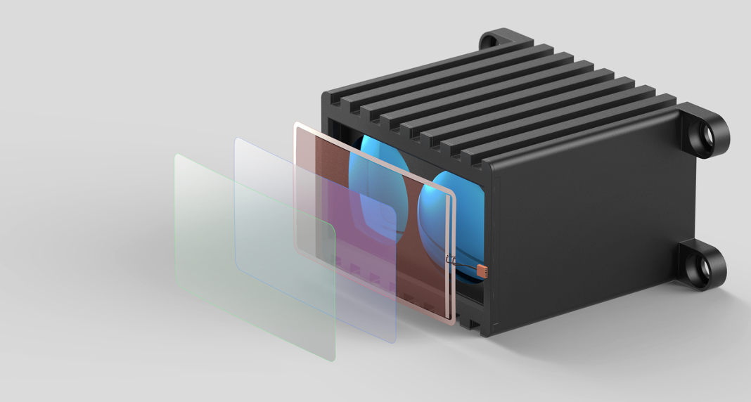
A transparent phased-array terminal has three components.
The radiating layer is a lithographically patterned array of transparent metamaterial-mesh elements deposited on an automotive-grade laminated-glass substrate, the same panoramic-roof or windscreen glass stack already in production at the major automotive glazing suppliers. The mesh forms the patch radiators, the feed network, the ground plane, and the impedance-matching structures. Element geometry, lattice pitch, and feed topology are designed for the Ku downlink (10.7–12.7 GHz) and Ku uplink (13.5–14.5 GHz) bands today, with a Ka-band roadmap (17.7–20.2 GHz downlink, 27.5–30.0 GHz uplink) accessible through the same patterning process at scaled lattice constants.
The edge-embedded active transceiver module is an opaque printed-circuit-board assembly housing the beamformer integrated circuits, the low-noise and power amplifiers, the local-oscillator and frequency-conversion stages, the digital control plane, and the interface to the vehicle’s communication bus. The module sits at the edge of the panoramic roof, within the body-in-white roof rail, the A-pillar, or the headliner, and is not visible to the cabin occupants. It is, deliberately, an opaque conventional PCB. The active electronics that a phased array requires cannot be made transparent, and our architectural decision is not to try.
The non-contact RF transition between the opaque transceiver PCB and the transparent radiating layer in the glass closes the loop. Conventional soldered RF connectors cannot be applied to transparent conductive films at the temperatures soldering requires, and conventional coaxial feedthroughs would be visible. The transition uses electromagnetic coupling, capacitive or proximity-fed, across the glass-to-PCB interface, with a coupling efficiency optimised for the operating band. It tolerates the mechanical and thermal cycling that the laminated-glass stack imposes, and it adds no visible feature to the cabin.
A real-time beamforming control loop closes around the architecture. Vehicle attitude (from the inertial measurement unit and GNSS), satellite ephemeris (broadcast from the ground or carried in the constellation’s signalling), and pilot-channel signal quality drive the phase-shifter settings across the array, maintaining lock on the target LEO satellite as it transits the sky. A ±60° field of view from boresight is sufficient to track a single LEO satellite for the few minutes it remains above a 30° elevation horizon; handover to the next satellite is supported by the option of a second simultaneous beam, which the architecture admits at modest additional cost.
Constellations served
The architecture is constellation-agnostic. The same transparent aperture, with the appropriate lattice scaling and front-end electronics, addresses essentially every operational and announced LEO and MEO broadband system:
- Starlink (SpaceX), the dominant commercial LEO system, with more than 7,000 satellites in orbit and over six million subscribers. User-link operation is in Ku-band (10.7–12.7 GHz down, 14.0–14.5 GHz up) and Ka-band (17.8–18.6 GHz, 18.8–19.3 GHz, 27.5–30.0 GHz). Starlink’s Mobility kits already serve vehicular customers; the transparent terminal addresses the premium passenger-car segment that the existing roof-mount kit cannot reach.
- Eutelsat OneWeb, a Ku-band Generation-1 LEO constellation of around 630 satellites in commercial service. The first-ever 5G-NTN trial over LEO, conducted in February 2025 by Eutelsat with MediaTek and Airbus, established Ku-band as the European LEO benchmark.
- Amazon Leo (formerly Project Kuiper), a 3,236-satellite Ka-band constellation in active deployment, with a public-beta service planned through 2026 and a three-tier user-terminal lineup (Leo Nano, Leo Pro, Leo Ultra). Amazon’s automotive roadmap will require a vehicle-side terminal that the published lineup does not yet include.
- Telesat Lightspeed, a Ka-band LEO constellation, 198-satellite Phase 1 starting deployment mid-2026, focused on enterprise and government broadband.
- SES O3b mPOWER, a high-throughput Ka-band MEO system. Higher latency than LEO, but addresses the same Ka-band user terminal and complements LEO constellations as a backhaul tier.
- IRIS², the European Union’s sovereign multi-orbit constellation of 264 LEO and 18 MEO satellites, contracted to the SpaceRISE consortium in December 2024, with services from 2030. The transparent-array architecture is well-aligned with IRIS²’s European-supply-chain and dual-use connectivity priorities.
- Geespace (Geely), a Chinese commercial LEO constellation purpose-built for the connected-car market, with vertical integration into Geely’s own vehicle programmes.
- Qianfan / Spacesail / G60, a Chinese LEO megaconstellation, more than 500 satellites launched of a planned 15,000.
- Guowang (China SatNet), a Chinese state-owned LEO constellation, 13,000-satellite target.
The two band families that the Orion mesh natively addresses, Ku and Ka, together cover every one of these systems. Direct-to-cell systems such as AST SpaceMobile and Lynk pursue a different architectural model that places the burden on the satellite side rather than the vehicle, and the transparent-array architecture is not aimed at that segment.
Why now
The connected-car connectivity envelope has been quietly converging on satellite. UN Regulation 157 and Euro NCAP 2026 protocols make a continuous, low-latency external link a practical prerequisite for Level 3+ autonomy certification, for both high-definition map updates and over-the-air software. The 3GPP NTN work programme, Release 17 (2022) the first 5G NR NTN normative specification, Release 18 adding TN–NTN mobility, Release 19 (late 2025) bringing regenerative payloads and store-and-forward, has put satellite tiers into mainline cellular standards. The 5GAA connected-vehicle service-level studies put high-definition-map delivery at 4 Mbps uplink / 16 Mbps downlink with 99.9 % availability and sub-100 ms latency, service envelopes that only a hybrid TN-plus-LEO solution can guarantee continuously. ESA’s autonomous-vehicle partnership project DARWIN measured 99 % session continuity for hybrid mobile-and-satellite connectivity across multi-environment trials.
So the question is no longer whether the connected car will use LEO satellite broadband, but which vehicle programmes will integrate it first, and what their endpoint antenna will look like. ESA’s April 2025 ARTES tender is the most explicit public statement that the European institutional view is the same: the technology is ready except for the vehicle-side antenna.
Application domains
In premium passenger cars, the panoramic glass roof is the natural aperture for the LEO terminal. The architecture preserves cabin aesthetics and aerodynamic profile, supports the high-definition-map and over-the-air-update connectivity requirements of Level 3+ programmes, and is compatible with the 5G NR NTN waveform that mainline 3GPP standards now specify. The OEM customer base spans major European brands, Japanese and Korean OEMs increasingly engaging with satellite connectivity, and Chinese OEMs vertically integrated with their own constellations, all of which have the connectivity demand pull, the integration capacity, and the design veto that requires a transparent terminal.
In commercial and fleet vehicles, the same architecture supports always-on telematics, fleet-management, and driver-assistance connectivity. The OEM design veto is weaker here, but the cost, reliability, and aerodynamic-drag arguments for an integrated transparent terminal remain strong, particularly for long-haul electric commercial vehicles where roof-mounted volume has a measurable energy cost.
In autonomous and robotaxi platforms, the connectivity envelope sharpens: high-bandwidth, low-latency, redundant LEO + terrestrial links become an operational requirement, not a convenience feature. The architecture’s compatibility with a second simultaneous beam, supporting inter-satellite handover without service interruption, is directly aligned with the service-continuity requirements that autonomous-driving certification will increasingly impose.
In government and emergency-services connectivity, police, fire, paramedic, military mobile-comms, civil-defence vehicles, the architecture provides unobtrusive, all-weather, sovereign-constellation-compatible connectivity that does not advertise the vehicle’s role through a visible roof-mounted antenna. This domain is a natural fit for the IRIS² roadmap and for European-sovereignty-focused procurements.
Contact us
If you are a Tier 1 supplier or OEM evaluating LEO satellite connectivity architecture for the next vehicle programme, the metamaterial mesh integrates with the panoramic roof and the windscreen in ways that are not possible with incumbent transparent conductors, and we would welcome conversations on programme-specific antenna design and integration.
If you are a LEO constellation operator or satellite-service provider, Starlink, Eutelsat OneWeb, Amazon Leo, Telesat Lightspeed, SES, the SpaceRISE / IRIS² consortium, or one of the Chinese constellation operators, the architecture closes the consumer-vehicle endpoint gap that is currently constraining the addressable market for vehicle satellite broadband.
If you are an ESA, EU, or national-agency programme manager working on automotive satcom, 3GPP NTN integration, or sovereign secure-connectivity initiatives, the technology is positioned for the ARTES SPL 5G/6G envelope, with public-sector funding and partnership routes that we are actively engaged with.
If you are an investor tracking the convergence of LEO satcom, automotive electronics, and metamaterials, the underlying market and partnership landscape that informed this article is available on request.
Reach out: info@oriondtech.com.